
Category: Electricity
Specification: PS-E-14
Document(s): Provisional Specification for the Approval of Electronic Current Transformers, PS-E-13
Distribution Date: 2007-06-25
Effective Date: 2007-06-25
Supersedes:
Table of contents
- 1.0 Scope
- 2.0 Authority
- 3.0 Description
- 4.0 Installation and use
- 5.0 Verification and reverification
- 6.0 Sealing
- 7.0 Documentation
- Appendix
1.0 Scope
These provisional specifications apply to the NXCT Electronic Current Transformer (NXCT) manufactured by NxtPhase Corporation. For combined electronic voltage and current transformers this specification will be applicable to the electronic current transformer.
2.0 Authority
These provisional specifications are issued under the authority of sections 12 and 18 of the Electricity and Gas Inspection Regulations.
3.0 Description
The NXCT is an electronic current transformer which uses optical technology (the Faraday effect) to measure line current, and transform the measured value to a proportionate secondary output.
4.0 Installation and use
4.1 General
4.1.1 Each verified NXCT to be installed and used in obtaining the basis of a charge shall be installed and used in the manner(s) established in the Notice of Approval (NOA) or Conditional NOA as applicable, in addition to that as specified in this document.
4.1.2 Each verified NXCT shall be installed and used in the manner established by the manufacturer's technical specifications and criteria.
4.2 Installation
4.2.1 The NXCT output shall be connected to a circuit where the combined burden of meter, associated wiring and connections, and any other secondary connected devices shall not exceed the approved burden designation as stated on the nameplate of the NXCT.
4.2.2 The NXCT shall be installed as a complete measurement device which incorporates each of its integrated metrological modules that are identified by its serial number on the verification/reverification documentation.
4.2.3 The NXCT output shall be connected to the input current circuits of an approved meter, and the minimum current rating of the meter installed shall not be greater than 4% of the output rating of NXCT which is connected to the meter input circuits.
4.2.4 The maximum current rating of the meter installed shall not be less than the rating factor of the connected NXCT times the secondary rating of the connected current transformer.
4.2.5 Each wire or cable that connects to the input of every metrological module of a NXCT shall be individually identifiable or traceable. Each wire or cable that connects from the output of the NXCT to a meter input shall be individually identifiable or traceable.
4.3 Use
4.3.1 The verification documentation and all subsequent reverification documentation shall be clearly legible, and readily available at the site location where the NXCT is being used.
4.3.2 Metrological modules identified by serial number on the verification/reverification documentation shall not be removed, replaced or modified under any circumstances with the exception stated as follows. Removal, replacement or modification of modules may be performed only in instances to correct for an error which resulted in rejection of the NXCT pursuant to the Reverification requirements of section 5.3. The NXCT shall subsequently be verified (either in-situ pursuant to section 5.4 or in test facility pursuant to section 5.2) prior to being used to obtain the basis for a charge.
4.3.3 Metrological components which are not specifically identified by serial number on the verification/reverification documentation shall not be installed on the NXCT.
4.3.4 The NXCT user manual shall be available on site upon request by Measurement Canada for the purposes of verification, reverification, installation inspection or dispute investigation.
5.0 Verification and reverification
5.1 General
5.1.1 Each NXCT to be verified or reverified shall comply with all terms and conditions established in the NOA, or Conditional NOA as applicable, in addition to all requirements established in this specification. Testing shall be performed in accordance with Measurement Canada requirements and the Procedures for the Verification and Reverification of NXCT Electronic Current Transformers.
5.1.2 NXCT electronic current transformers shall be reverified for compliance with the requirements of these specifications within a maximum of eight (8) years subsequent to the previous verification/reverification.
5.1.3 Additional reverification testing of any NXCT which is approved conditionally shall be performed at any time as required by Measurement Canada throughout the device's period of operation in service, and such reverification shall be performed pursuant to 5.1.1.
5.1.4 The calibration uncertainty value included within the accuracy class limit shall be less than one third of the specified accuracy class. For example, for a 0.3% class CT, the uncertainty of the calibration system including the Reference CT and Comparator shall be less than 0.1%.
5.2 Verification
Verification of this device type is performed with two distinct objectives. The first is to ascertain transformer correction factor (TCF) over the operating range of the device and determine if it complies with the specified limits of error. The second is to determine metrological module characteristics as they exist at the time TCF is determined. The purpose of this second objective is to have comparative data which will be used to assess the device during subsequent reverification testing. The premise being applied at reverification is that if the characteristics of the metrological modules do not deviate more than a specified value, this is an indication that the TCF for this device type will also remain within the limits specified for verification.
5.2.1 Optical wavelength of light source
5.2.1.1 Wavelength shall be measured three successive times and the weighted average determined, and recorded.
5.2.1.2 The wavelength information from the original verification shall be secured and stored within the electronic chassis of the NXCT for future comparative reference during reverification.
5.2.2 Amplifier output
5.2.2.1 Output current shall be compared to input voltage at the following four test points; 5%, 10%, 50% and 100% of the rated current as marked on the nameplate of the device under test.
5.2.2.2 The input voltage, output current, amplifier gain and phase shift shall be documented for each test point.
5.2.3 Temperature sensor
5.2.3.1 The temperature sensor in the cable management box shall be tested at the following three test points; -40, +25, and +60 degrees Celsius.
5.2.3.2 Temperatures determined by the device under test shall not differ from true temperature by more than +7 degrees Celsius.
5.2.3.3 All values of true temperature and registered temperature shall be recorded.
5.2.4 Transformer correction factor (TCF)
5.2.4.1 TCF shall be determined with the corresponding burden for its approved accuracy class applied. Refer to Table 1, table 2 and table 3 of the Appendix.
5.2.4.2 TCF shall be determined at the following four test points; 5%, 10%, 50% and 100% of the rated value of current as marked on the nameplate of the device under test.
5.2.4.3 Measured values at each test point shall comply with the limiting values established by the parallelogram in Figure 1 of the Appendix for the applicable accuracy class of the device under test.
5.3 Reverification
The premise for reverification test criteria, as stated in section 5.2, is based on a comparative assessment of the characteristics of the metrological modules. Where the assessment determines that those measured values have remained sufficiently stable within specified limits, the device accuracy is also deemed to be within specified limits for its approved accuracy class.
In situations where any of the modules are not in compliance with the specified limits, the NXCT is deemed to be operating outside its approved accuracy class and is therefore non-compliant with the specified requirements. The NXCT shall subsequently be verified (either in-situ pursuant to section 5.4 or in test facility pursuant to section 5.2) prior to being used to obtain the basis for a charge.
5.3.1 Optical wavelength of light source
5.3.1.1 Wavelength shall be measured three successive times and the weighted average determined, and recorded.
5.3.1.2 The weighted average wavelength determined at reverification shall not differ from wavelength determined at initial verification or any subsequent reverification by more than 0.15% (i.e. +2 nm) for a class 0.3 device, and not by more than 0.1% (i.e. +1 nm) for a class 0.15 device.
5.3.2 Amplifier output
5.3.2.1 Output current shall be compared to input voltage at the following four test points; 5%, 10%, 50% and 100% of the rated current as marked on the nameplate of the device under test.
5.3.2.2 The input voltage, output current, amplifier gain and phase shift shall be documented for each test point.
5.3.2.3 The magnitude of amplifier gain determined at reverification shall not differ from the magnitude determined at initial verification or any subsequent reverification by more than 0.15% for a class 0.3 device and not by more than 0.1% for a class 0.15 device.
5.3.2.4 The phase shift between input voltage and output current determined at reverification shall not differ from the phase shift determined at initial verification or any subsequent reverification by more than 6 minutes, (0.1 degrees) for a class 0.3 device and not by more than 3 minutes, (0.05 degrees) for a class 0.15 device.
5.3.3 Temperature sensor
5.3.3.1 The temperature sensor in the cable management box shall be assessed for compliance at prevailing ambient temperature.
5.3.3.2 Temperature determined by the device under test shall not differ from true temperature by more than + 7 degrees Celsius.
5.3.3.3 In addition to the established limit of error, the error determined at reverification shall not differ from any of the errors determined at initial verification or any subsequent reverification by more than + 4 degrees Celsius.
5.4 In-situ verification
In-situ verification may take place only in circumstances where the NXCT has been determined to be non-compliant with the reverification requirements specified in, and pursuant to, section 5.3. In-situ verification requirements are based on the verification requirements specified in section 5.2, however have been adapted slightly such that devices which have been deemed non-compliant pursuant to section 5.3 may be eligible to be verified in-situ. Two acceptable methods for determining TCF are available.
5.4.1 Optical wavelength of light source and amplifier output
These metrological modules shall be assessed as specified in sections section 5.2.1 and 5.2.2.
5.4.2 Temperature sensor
In situations where the temperature sensor was found to be compliant with the Reverification requirements (section 5.3.3), and no changes have been made to the temperature sensor subsequent to initial verification of the NXCT, then it is considered to be in continued compliance with the verification requirements of section 5.2. In any other situations the temperature sensor shall be assessed as specified in section 5.2.3.
5.4.3 Transformer correction factor (TCF)—not requiring power outage
5.4.3.1 TCF shall be determined with the applied burden which is connected at the installation.
5.4.3.2 TCF shall be determined at prevailing line current at a minimum of two test points within the operating range of the device under test.
5.4.3.3 One test point shall be between 5% and 10% of the rated value of current as marked on the nameplate of the device under test.
5.4.3.4 One test point shall be between 50% and 100% of the rated value of current as marked on the nameplate of the device under test.
5.4.3.5 Measured values at each test point shall comply with the limiting values established by the parallelogram in Figure 1 of the Appendix for the applicable accuracy class of the device under test.
5.4.4 Transformer correction factor (TCF)—requiring power outage
5.4.4.1 TCF shall be determined with the applied burden which is connected at the installation.
5.4.4.2 TCF shall be determined at the following four test points; 5%, 10%, 50% and 100% of the rated value of current as marked on the nameplate of the device under test.
5.4.4.3 Measured values at each test point shall comply with the limiting values established by the parallelogram in Figure 1 of the Appendix for the applicable accuracy class of the device under test.
6.0 Sealing
6.1 Sealing shall be performed in the manner stated in the Notice of Approval.
6.2 It shall not be possible to modify any metrological parameters without breaching the seal(s) subsequent to the sealing of a verified NXCT.
7.0 Documentation
In addition to the certificate of verification as required pursuant to section 14 of the Electricity and Gas Inspection Act, additional verification/reverification information must be documented and available at the installation location in order to facilitate the in-situ test provisions provided for in this specification.
The NXCT verification/reverification documentation shall include the following data for verification and each subsequent re-verification:
- Temperature values at initial verification and each subsequent reverification
- Wavelength values at initial verification and each subsequent reverification
- Amplifier gain values at initial verification and each subsequent reverification
- TCF (including magnitude and phase angle errors) at initial verification and each subsequent reverification
- Any non-compliance with any of the requirements in these specifications, including errors exceeding specified limits
- All scale factors including coarse gain, precise gain, and phase. (These must also be stored in the electronic chassis)
- Serial numbers for each of the following metrological components, including all metrological components subject to individual component testing:
- The current transformer head
- The electro-optics module
- The amplifier(s)
- The temperature sensor
- The structural column
- Maximum primary current rating of the device
- Date and location of verification/reverification
- Identification of standards and test equipment used
- Identification of the inspector or accredited meter verifier who performed the verification/reverification
Alan E. Johnston
President
Appendix
Figure 1–Limits for measuring current transformer
Limits of 0.15 accuracy class
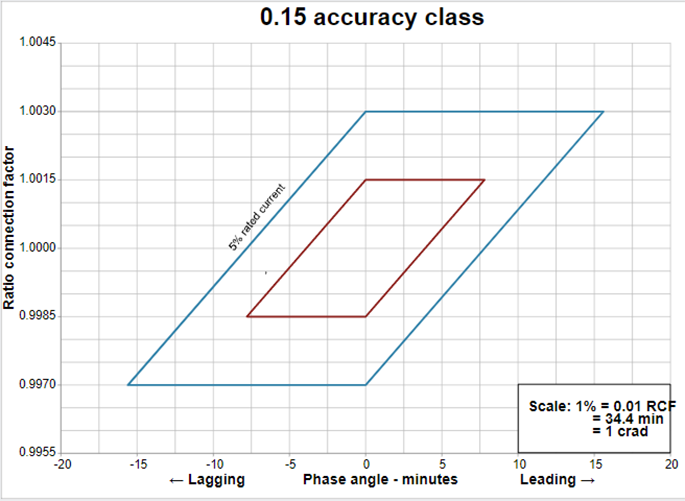
Description of limits of 0.15 accuracy class figure
The relationships between the limits of the ratio correction factors and the phase angle for the limiting values of the transformer correction factors (TCFs) specified in Table 3 are provided by parallelograms that are plotted on graphs in which a phase angle correction factor in minutes appears on the x-axis and a ratio correction factor appears on the y-axis. The parallelograms defining the limiting values of the TCFs for current transformers are bound by vertices. For a 0.15 accuracy class at a 5% rated current, the limiting values are (0, 1.003), (15.6, 1.003), (0, 0.997) and (-15.6, .997). At a 100% rated current, the limiting values are (0, 1.0015), (7.8, 1.0015), (0, 0.9985) and (-7.8, 0.9985).
Limits of 0.3 accuracy class
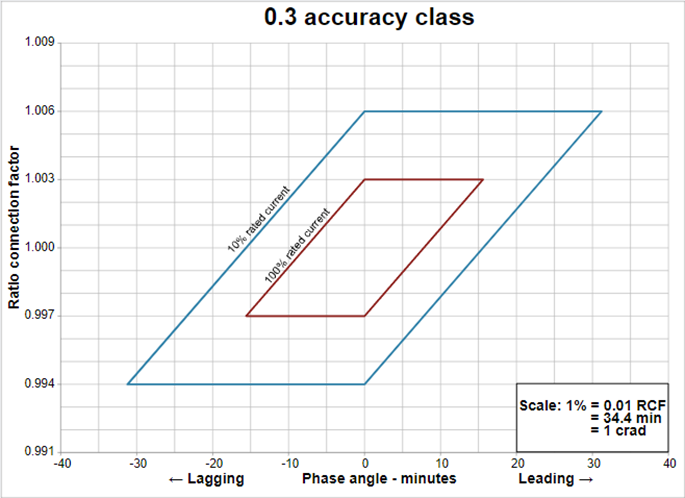
Description of imits of 0.3 accuracy class figure
The relationships between the limits of the ratio correction factors and the phase angle for the limiting values of the transformer correction factors (TCFs) specified in Table 3 are provided by parallelograms that are plotted on graphs in which a phase angle correction factor in minutes appears on the x-axis and a ratio correction factor appears on the y-axis. The parallelograms defining the limiting values of the TCFs for current transformers are bound by vertices. For a 0.3 accuracy class at a 10% rated current, the limiting values are (0, 1.006), (31.2, 1.006), (0, 0.994) and (-31.2, 0.994). At a 100% rated current, the limiting values are (0, 1.003), (15.6, 1.003), (0, 0.997) and (-15.6, 0.997).
Limits of 0.6 accuracy class

Description of limits of 0.6 accuracy class figure
The relationships between the limits of the ratio correction factors and the phase angle for the limiting values of the transformer correction factors (TCFs) specified in Table 3 are provided by parallelograms that are plotted on graphs in which a phase angle correction factor in minutes appears on the x-axis and a ratio correction factor appears on the y-axis. The parallelograms defining the limiting values of the TCFs for current transformers are bound by vertices. For a 0.6 accuracy class at a 10% rated current, the limiting values are (0, 1.012), (62.4, 1.012), (0, 0.988) and (62.4, 0.988). At a 100% rated current, the limiting values are (0, 1.006), (31.2, 1.006), (0, 0.994) and (31.2, 0.994)