
Category: Electricity
Specification: S-E-07 (rev. 1)
Document(s):
Issue date: 2016-05-24
Effective date: 2016-07-01
Supersedes: S-E-07
Table of contents
- 1.0 Scope
- 2.0 Authority
- 3.0 References
- 4.0 Definitions
- 5.0 Ratings
- 6.0 Design requirements
- 7.0 Markings
- 8.0 Accuracy
- 9.0 Revision
1.0 Scope
These specifications apply to instrument transformers which are intended to be used in revenue metering. Specifications for current transformers are applicable only for solid core devices.
2.0 Authority
These specifications are issued pursuant to subsection 12(1) of the Electricity and Gas Inspection Regulations.
3.0 References
3.1 Electricity and Gas Inspection Act (R.S. 1985, c. E-4), subsection 9(4)
3.2 Electricity and Gas Inspection Regulations (SOR/86-131), subsection 12(1)
3.3 CAN/CSA-C61869-1:14 Part 1 Instrument transformers – Part 1: General requirements
3.4 CAN/CSA-C61869-2:14 Instrument transformers – Part 2: Additional requirements for current transformers
3.5 CAN/CSA-C61869-3:14 Instrument transformers – Part 3: Additional requirements for inductive voltage transformers
3.6 CAN/CSA-C61869-4:14 Instrument transformers – Part 4: Additional requirements for combined transformers
3.7 CAN/CSA-C61869-5:15 Instrument transformers – Part 5: Additional requirements for capacitor voltage transformers
4.0 Definitions
- Accuracy class
-
A designation assigned to a measuring instrument transformer the errors of which remain within specified limits under prescribed conditions of use.
- Accuracy-rating voltage
-
The normal operating voltage of a voltage transformer upon which the accuracy performance is based.
- Burden
-
The property of the circuit connected to the secondary winding that determines the active and reactive power at the secondary terminals. The burden is expressed either as total ohms impedance with the effective resistance and reactance components, or as the total volt-amperes and power factor at the specified value of current or voltage, and frequency.
- Capacitor voltage transformer
-
A voltage transformer comprising a capacitor divider unit and an electromagnetic unit so designed and connected that the secondary voltage of the electromagnetic unit is substantially proportional to the primary voltage, and differs in phase from it by an angle which is approximately zero for an appropriate direction of connections and rated frequency.
- Combined instrument transformer
-
A combination of voltage and current measuring transformers in a single tank or assembly. Also known as a "metering outfit".
- Continuous thermal current rating factor
-
The number by which the rated primary current of a measuring current transformer is multiplied to obtain the maximum primary current that can be carried continuously without exceeding either the limiting temperature rise from 30 °C average ambient air temperature or the rated accuracy. The rating factor may be 1.0, 1.25, 1.33, 1.5, 2.0, 3.0 and 4.0. The rating factor of tapped-secondary or multi-ratio transformers applies to the highest ratio, unless otherwise stated.
- Current transformer
-
A measuring instrument transformer in which the secondary current, in normal conditions of use, is substantially proportional to the primary current and differs in phase from it by an angle which is approximately zero for an appropriate direction of the connections.
- Double-primary current transformer
-
A current transformer equipped with two primary windings suitable for series or parallel connection and common to all secondary coils and magnetic circuits.
- Double-ratio current transformer
-
A multi-ratio current transformer which has two ratios which are in the ratio of two to one.
- Double-secondary current transformer
-
One current transformer which has two secondary coils each on a separate magnetic circuit with both magnetic circuits excited by the same primary winding or windings. The secondary coils may be tapped or untapped.
- Double-secondary voltage transformer
-
One voltage transformer which has two secondary windings on the same magnetic circuit insulated from each other and the primary. Either or both of the secondary windings may be used for measurement or control.
- Dual-ratio current transformer
-
A multi-ratio current transformer having two ratios which are not necessarily in the relation of two to one.
- Highest voltage for equipment
-
The highest continuous root-mean-square steady-state voltage for which the equipment insulation is designed.
- Instrument transformer
-
A measuring transformer which is intended to reproduce in its secondary circuit, in a definite and known proportion, the current or voltage of its primary circuit with the phase relations substantially preserved.
- Marked ratio
-
The ratio of the rated primary value to the rated secondary value as stated on the nameplate.
- Multi-ratio current transformer
-
One current transformer from which more than one ratio can be obtained by the use of taps or series-multiple connection.
- Multiple secondary current transformer
-
One current transformer which has three or more secondary coils each on a separate magnetic circuit with all magnetic circuits excited by the same primary winding.
- Percent ratio error of an instrument transformer
-
The difference between the ratio correction factor and unity expressed in per cent.
- Phase angle correction factor
-
The ratio of the true power factor to the measured power factor. It is a function of both the phase angle of the instrument transformer and the power factor of the primary circuit being measured.
Note: The phase angle correction factor is the factor which corrects for the phase displacement of the current or voltage or both, due to the instrument transformer phase angle. The measured watts or watt hours in the secondary circuits of instrument transformers must be multiplied by the phase angle correction factor and the true ratio to obtain the true primary watts or watt hours.
- Phase angle of an instrument transformer
-
The phase displacement between the primary and secondary values.
Note: The phase angle of a current transformer is designated by the Greek letter beta (β) and is positive when the current leaving the identified secondary terminal leads the current entering the identified primary terminal.
For example:
- , where β approximates the phase angle in minutes; and
- , where β approximates the phase angle in radians.
Where: RCF is the ratio correction factor and TCF is the transformer correction factor
Note: The phase angle of a voltage transformer is designated by the Greek letter gamma (γ) and is positive when the voltage at the identified secondary terminal leads the voltage at the identified primary terminal.
For example:
- , where γ approximates the phase angle in minutes; and
- , where γ approximates the phase angle in radians.
Where: RCF is the ratio correction factor and TCF is the transformer correction factor
- Rated insulation level
-
The combination of voltage values which characterize the insulation of an instrument transformer to withstand dielectric stresses.
- Rated output
-
The value of the apparent power (in volt-amperes at a specific power factor) which the transformer is intended to supply to the secondary circuit at the rated secondary current or voltage and with rated burden connected to it.
- Rated primary current of a current transformer
-
The current selected for the basis of performance specifications.
- Rated primary voltage of a voltage transformer
-
The voltage selected for the basis of performance specifications.
- Rated secondary current
-
The rated primary current divided by the marked ratio.
- Rated secondary voltage
-
The rated primary voltage divided by the marked ratio.
- Ratio correction factor
-
The ratio of the true ratio to the marked ratio. The primary current or voltage is equal to the secondary current or voltage multiplied by the marked ratio times the ratio correction factor.
- Symbols for current transformer
-
Symbols for measuring current transformer ratio designation as per Table 201A of CAN/CSA- 61869-2:14 shall be applicable.
- Accuracy designation for current transformer
-
Accuracy designation for current transformers shall be such that the accuracy class is identified, followed by the letter B, followed by the maximum standard burden applicable for the accuracy rating.
- Symbols for voltage transformer
-
Voltage transformer symbols for ratio designation as per the CSA column of Table 301A of CAN/CSA- 61869-3:14 shall be applicable.
- Accuracy designation for voltage transformer
-
Accuracy designation for voltage transformers shall be such that the accuracy class is identified, followed by all the standard burdens applicable for the accuracy rating.
- Accuracy designation for voltage transformer
-
Accuracy designation for voltage transformers shall be such that the accuracy class is identified, followed by all the standard burdens applicable for the accuracy rating.
Note
Example:
- 0.3WXYZ
- 0.3% accuracy for a burden of 200 VA
WXYZ are standard burdens in accordance with Table 3 in section 5.2.2.
- Three-wire current transformer
-
A current transformer which has two separate primary windings each completely insulated for the rated insulation level of the transformer. This type of current transformer is for use on a three-wire, single-phase service.
Note: These transformers may have two primary windings, one secondary winding and one core assembled as a single unit; or have two primary windings, two secondary windings and two cores assembled as separate units and mounted on one base with the secondaries connected permanently in parallel to a single terminal block. The secondary current in both cases is proportional to the phasor sum of the primary currents.
- Transformer correction factor
-
The ratio correction factor multiplied by the phase angle correction factor for a specified primary circuit power factor.
- True ratio
-
The ratio of the root-mean-square primary value to the root-mean-square secondary value under specified conditions, with sinusoidal current or voltage in the primary winding.
- Type
-
The manufacturer's designation for transformers having different nominal currents or voltages, but which are similar in:
- measurement characteristics
- model and construction
- Voltage classification
-
The level of power frequency voltage which identifies the system of insulation levels and associated tests applicable to the transformer.
- Voltage transformer
-
A measuring instrument transformer in which the secondary voltage, in normal conditions of use, is substantially proportional to the primary voltage and differs from it by an angle which is approximately zero for an appropriate direction of the connections.
5.0 Ratings
5.1 Current transformer
All current transformers shall meet the following requirements:
5.1.1 Preferred current ratings shall be according to the values in Tables 201F and 20G of CAN/CSA 61869-2:14.
5.1.2 Standard burdens for current transformers shall be according to the values in Tables 1 and 2 below.
| Standard burden | Characteristics | Characteristics for 60 Hz 5 A secondary current | |||
|---|---|---|---|---|---|
| Resistance Ω | Inductance mH | Impedance Ω | V·A | Power factor | |
| E-0.04 | 0.04 | 0.0 | 0.04 | 1 | 1.0 |
| E-0.2 | 0.20 | 0.0 | 0.20 | 5 | 1.0 |
| B0.1 | 0.09 | 0.116 | 0.1 | 2.5 | 0.9 |
| B0.2 | 0.18 | 0.232 | 0.2 | 5.0 | 0.9 |
| B0.5 | 0.45 | 0.580 | 0.5 | 12.5 | 0.9 |
| B0.9 | 0.81 | 1.044 | 0.9 | 22.5 | 0.9 |
| B1.8 | 1.62 | 2.088 | 1.8 | 45.0 | 0.9 |
| Standard burden | Characteristics | Characteristics for 60 Hz 1 A secondary current | |||
|---|---|---|---|---|---|
| Resistance Ω | Inductance mH | Impedance Ω | V·A | Power factor | |
| E-0.01 | 0.25 | 0.0 | 0.25 | 0.25 | 1.0 |
| E-0.04 | 1 | 0.0 | 1.0 | 1 | 1.0 |
| E-0.2 | 5 | 0.0 | 5.0 | 5 | 1.0 |
| B0.1 | 2.25 | 2.9 | 2.5 | 2.5 | 0.9 |
| B0.2 | 4.5 | 5.8 | 5.0 | 5.0 | 0.9 |
| B0.5 | 11.25 | 14.5 | 12.5 | 12.5 | 0.9 |
| B0.9 | 20.25 | 26.1 | 22.5 | 22.5 | 0.9 |
| B1.8 | 40.5 | 52.2 | 45.0 | 45.0 | 0.9 |
5.2 Voltage transformer
All voltage transformers shall meet the following requirements:
5.2.1 Only rated secondary voltages of 120 V and 115 V shall be approved for measuring applications.
5.2.2 Preferred voltage ratings shall be according to the values in Tables 301F and 301G of CAN/CSA 61869-3:14.
5.2.3 Standard burdens for voltage transformers shall be according to the values in Table 3 below.
| Standard burden | Characteristics on 120 V basis | ||||
|---|---|---|---|---|---|
| Designation | VA | PF | Resistance Ω | Inductance H | Impedance Ω |
| Q | 1.0 | 1 | 14400 | 0 | 14400 |
| T | 2.5 | 1 | 5760 | 0 | 5760 |
| W | 12.5 | 0.1 | 115.2 | 3.042 | 1152 |
| X | 25 | 0.7 | 403.2 | 1.092 | 576 |
| Y | 75 | 0.85 | 163.2 | 0.268 | 192 |
| Z | 200 | 0.85 | 61.2 | 0.101 | 72 |
| ZZ | 400 | 0.85 | 30.6 | 0.0504 | 36 |
6.0 Design requirements
6.1 Temperature rise
6.1.1 Current transformer – Temperature rise of current transformers shall meet the requirement of section 6.4 of CAN/CSA 61869-1:14.
6.1.2 Voltage transformer – Temperature rise of voltage transformers shall meet the requirement of section 6.4 of CAN/CSA 61869-1:14.
6.2 Insulation
6.2.1 Current transformer – Insulation level for current transformers shall meet the requirement of section 5.3 of CAN/CSA 61869-1:14.
6.2.2 Voltage transformer – Insulation level for voltage transformers shall meet the requirement of section 5.3 of CAN-CSA 61869-1:14.
7.0 Markings
7.1 Terminal markings
In general, terminal markings shall identify the primary and secondary windings, the winding sections (if any), the relative polarities of windings and winding sections, and the intermediate tappings (if any).
7.1.1 Current transformer – Terminal markings of current transformers shall meet Canadian marking requirements of sections 6.13.201 and 6.13.201.4 of CAN/CSA 61869-2:14.
7.1.2 Voltage transformer – Terminal markings of inductive voltage transformers shall meet Canadian marking requirements of sections 6.13.301.3 and 6.13.301.4 of CAN/CSA 61869-3:14. Terminal markings of capacitor voltage transformers shall meet Canadian marking requirements of section 6.13.501 of CAN/CSA 61869-5:15.
7.1.3 Combined transformer – Terminal markings of combined transformers shall meet Canadian marking requirements of section 6.13.401 of CAN/CSA 61869-4:14.
7.2 Nameplate
7.2.1 Nameplate positioning (general) – The nameplate of measuring instrument transformers shall be attached so as to be clearly visible or easily accessible. If the transformer is contained within another device such as a power transformer or a metering outfit, the nameplate shall be mounted on the exterior of the device in such a manner as to be readily visible (i.e. on the measuring element or base). The nameplate shall not be mounted on the terminal cover unless the cover remains permanently attached to the exterior of the transformer by a physical means such as a non-removable hinge or similar arrangement.
7.2.2 Current transformer – Where applicable, nameplates of current transformers shall include, as a minimum, the following:
- Manufacturer's name or trademark
- Manufacturer's type
- Manufacturer's serial number
- Rated frequency
- Rated primary and secondary currents
- Voltage classification
- Continuous thermal current rating factor
- Approved measuring accuracy ratingFootnote *
- Approval number
7.2.3 Voltage transformer – Where applicable, nameplates of voltage transformers shall include, as a minimum, the following:
- Manufacturer's name or trademark
- Manufacturer's type
- Manufacturer's serial number
- Rated frequency
- Rated primary and secondary voltages
- Voltage classification
- Lightning impulse level
- Rated voltage factor and rated time
- Approved measuring accuracy rating
- Approval number
8.0 Accuracy
8.1 Current transformers
8.1.1 Assignment of accuracy class – A measuring current transformer shall be given an accuracy class as specified in Table 4 for each standard burden (Tables 1 and 2) up to the maximum for which it is designed. For multi ratio current transformers, if only one accuracy rating is assigned, it shall apply to all ratios.
8.1.2 Basis for measurement accuracy classes – Accuracy classes for measuring current transformers are based on the requirement that the transformer correction factor (TCF) be within specified limits for the following conditions:
- 100% of rated primary current or the corresponding continuous current factor;
- 10% or 5% of rated primary current;
- power factor (lagging) of metered power load from 0.6 to 1.0;
- burden of a specific standard value; and
- normal service conditions.
Note
At 5% or 10% of rated primary current, the permissible error is twice the permissible error at 100% rated primary current.
The relationships between the limits of the ratio correction factors (RCFs) and the phase angle for the limiting values of the TCFs specified in Table 4 are shown in the parallelograms in Figure 1.
| Accuracy class | 100% rated current* | 10% rated current | 5% rated current | Limits of power factor (lag) of metered power load |
|---|---|---|---|---|
| 0.15 | 0.9985–1.0015 | 0.997–1.003 | 0.6–1 | |
| 0.3 | 0.997–1.003 | 0.994–1.006 | 0.6–1 | |
| 0.6 | 0.994–1.006 | 0.988–1.012 | 0.6–1 |
Note
These limits also apply at the maximum continuous current rating factor (RF). The RF can be 1.0, 1.25, 1.33, 1.5, 2.0, 3.0 or 4.0.
Figure 1–Limits for measuring current transformer
Limits of 0.15 accuracy class
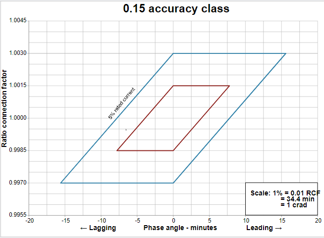
Description of limits of 0.15 accuracy class figure
The relationships between the limits of the ratio correction factors and the phase angle for the limiting values of the transformer correction factors (TCFs) specified in Table 4 are provided by parallelograms that are plotted on graphs in which a phase angle correction factor in minutes appears on the x-axis and a ratio correction factor appears on the y-axis. The parallelograms defining the limiting values of the TCFs for current transformers are bound by vertices. For a 0.15 accuracy class at a 5% rated current, the limiting values are (0, 1.003), (15.6, 1.003), (0, 0.997) and (-15.6, .997). At a 100% rated current, the limiting values are (0, 1.0015), (7.8, 1.0015), (0, 0.9985) and (-7.8, 0.9985).
Limits of 0.3 accuracy class
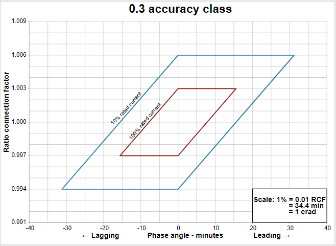
Description of imits of 0.3 accuracy class figure
The relationships between the limits of the ratio correction factors and the phase angle for the limiting values of the transformer correction factors (TCFs) specified in Table 4 are provided by parallelograms that are plotted on graphs in which a phase angle correction factor in minutes appears on the x-axis and a ratio correction factor appears on the y-axis. The parallelograms defining the limiting values of the TCFs for current transformers are bound by vertices. For a 0.3 accuracy class at a 10% rated current, the limiting values are (0, 1.006), (31.2, 1.006), (0, 0.994) and (-31.2, 0.994). At a 100% rated current, the limiting values are (0, 1.003), (15.6, 1.003), (0, 0.997) and (-15.6, 0.997).
Limits of 0.6 accuracy class
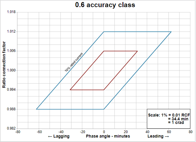
Description of limits of 0.6 accuracy class figure
The relationships between the limits of the ratio correction factors and the phase angle for the limiting values of the transformer correction factors (TCFs) specified in Table 4 are provided by parallelograms that are plotted on graphs in which a phase angle correction factor in minutes appears on the x-axis and a ratio correction factor appears on the y-axis. The parallelograms defining the limiting values of the TCFs for current transformers are bound by vertices. For a 0.6 accuracy class at a 10% rated current, the limiting values are (0, 1.012), (62.4, 1.012), (0, 0.988) and (62.4, 0.988). At a 100% rated current, the limiting values are (0, 1.006), (31.2, 1.006), (0, 0.994) and (31.2, 0.994)
8.2 Voltage transformers
8.2.1 Assignment of accuracy class – A measuring voltage transformer shall be given an accuracy class as specified in Table 5 for each standard burden in Table 3, up to the maximum for which it is designed.
8.2.2 Accuracy class for multi-ratio measuring voltage transformers – Where a single accuracy designation is specified for transformers with secondary and tertiary windings (e.g., in the form 0.3Z), the accuracy requirement shall only apply to the secondary winding when the tertiary winding is not loaded, to the tertiary winding when the secondary winding is not loaded, and to both windings when the designated burden is divided in any proportion between the two windings. Where a double accuracy designation is specified (e.g., in the form 0.6Z-0.6Z), the first designation shall apply to the secondary winding and the other to the tertiary shall apply when the tertiary winding is either not loaded or loaded with its designated burden, and the accuracy requirement for the tertiary winding shall apply when the secondary winding is either not loaded or loaded with its designated burden.
8.2.3 Basis for measurement accuracy classes – Accuracy classes for measuring voltage transformers are based on the requirement that the TCF be within specified limits for the following conditions:
- 90% to 110% of accuracy-rated voltage;
- Voltage corresponding to the continuous rating factor as per Table 304, as referenced in CAN/CSA 61869-3:14;
- Power factor (lagging) of metered power load from 0.6 to 1.0;
- Burden of a specified standard value; and
- Indicated service conditions.
The relationships between the limits of the ratio correction factors and the phase angle for the limiting values of the TCFs specified in Table 5 are shown in the parallelogram in Figure 2.
| Accuracy classes | Limits of TCF for 90% to 110% Accuracy-rating voltage Footnote 2 | Limits of power factor (lag) of metered power load | |
|---|---|---|---|
| Minimum | Maximum | ||
| 0.15 | 0.9985 | 1.0015 | 0.6-1 |
| 0.3 | 0.997 | 1.003 | 0.6-1 |
| 0.6 | 0.994 | 1.006 | 0.6-1 |
Figure 2–Limits for measuring voltage transformer
Limits of 0.15 accuracy class
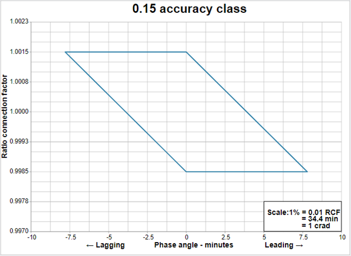
Description of limits of 0.15 accuracy class figure
The relationships between the limits of the ratio correction factors and the phase angle for the limiting values of the transformer correction factors (TCFs) specified in Table 5 are provided by parallelograms that are plotted on graphs in which a phase angle correction factor in minutes appears on the x-axis and a ratio correction factor appears on the y-axis. The parallelograms defining the limiting values of the TCFs for voltage transformers are bound by vertices. For a 0.15 accuracy class the limiting values are (0, 1.0015), (7.8, 1.0015), (0, 0.9985) and (7.8, 0.9985).
Limits of 0.3 accuracy class
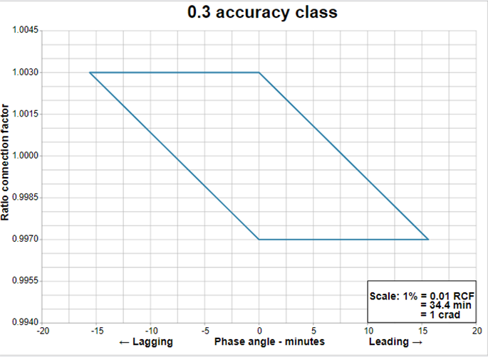
Description of limits of 0.3 accuracy class figure
The relationships between the limits of the ratio correction factors and the phase angle for the limiting values of the transformer correction factors (TCFs) specified in Table 5 are provided by parallelograms that are plotted on graphs in which a phase angle correction factor in minutes appears on the x-axis and a ratio correction factor appears on the y-axis. The parallelograms defining the limiting values of the TCFs for voltage transformers are bound by vertices. For a 0.3 accuracy class the limiting values are (0, 1.003), (15.6, 1.003), (0, 0.997) and (15.6, 0.997).
Limits of 0.6 accuracy class

Description of limits of 0.6 accuracy class figure
The relationships between the limits of the ratio correction factors and the phase angle for the limiting values of the transformer correction factors (TCFs) specified in Table 5 are provided by parallelograms that are plotted on graphs in which a phase angle correction factor in minutes appears on the x-axis and a ratio correction factor appears on the y-axis. The parallelograms defining the limiting values of the TCFs for voltage transformers are bound by vertices. For a 0.6 accuracy class the limiting values are (0, 1.006), (31.2, 1.006), (0, 0.994) and (31.2, 0.994).
9.0 Revision
The purpose of revision 1 is to make clarifications to the parallelogram of Figure 1: Limits of 0.15 accuracy class for measuring current transformers. This revision also includes updates to align with applicable requirements found in the CAN/CSA-C61869 series of requirements.